The FPR1010-NGFW-K9 is one of the Cisco Firepower 1010 network security appliances in the Cisco Firepower family. The Firepower 1010 is first supported in Firepower Threat Defense (FTD) Version 6.4 and ASA Version 9.12. PoE+ and L2 switch support were added beginning with FTD Version 6.5 and ASA Version 9.13.
Console Ports of The FPR1010-NGFW-K9 Appliances
The Firepower FPR1010-NGFW-K9 has two external console ports, a standard RJ-45 port and a USB Mini B serial port. Only one console port can be active at a time. When a cable is plugged into the USB console port, the RJ-45 port becomes inactive. Conversely, when the USB cable is removed from the USB port, the RJ-45 port becomes active. The console ports do not have any hardware flow control. You can use the CLI to configure the chassis through either serial console port by using a terminal server or a terminal emulation program on a computer.
- RJ-45 (8P8C) port—Supports RS-232 signaling to an internal UART controller. The RJ-45 console port does not support a remote dial-in modem. You can use a standard management cable (Cisco part number 72-3383-01) to convert the RJ45-to-DB9 connection if necessary.
- USB Mini B port—Lets you connect to a USB port on an external computer. For Linux and Macintosh systems, no special driver is requi red. For Windows systems, you must download and install a USB driver (available on software.cisco.com). You can plug and unplug the USB cable from the console port without affecting Windows HyperTerminal operations. We recommend shielded USB cables with properly terminated shields. Baud rates for the USB console port are 1200, 2400, 4800, 9600, 19200, 38400, 57600, and 115200 bps.
The FPR1010-NGFW-K9 Package Contents
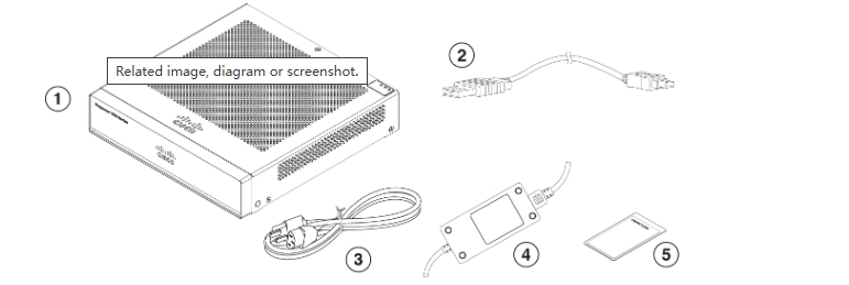
1 | Chassis | 2 | USB console cable (Type A to Mini Type B) Part number 37-1977-01 (Optional; in package if ordered) |
3 | Power cord | 4 | Power supply |
5 | Cisco Secure Firepower 1010 This document has a URL and QR code that point to the Digital Documentation Portal. The portal contains links to the product information page, the hardware installation guide, the regulatory and safety information guide, the getting started guide, and the easy deployment guide. | | — |
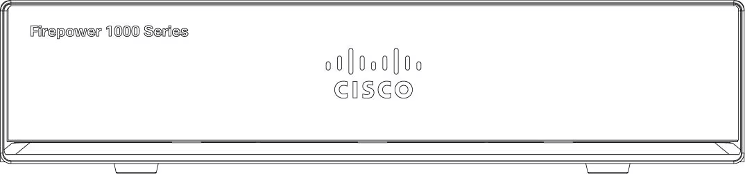
The FPR1010-NGFW-K9 Front Panel
The FPR1010-NGFW-K9 Rear Panel
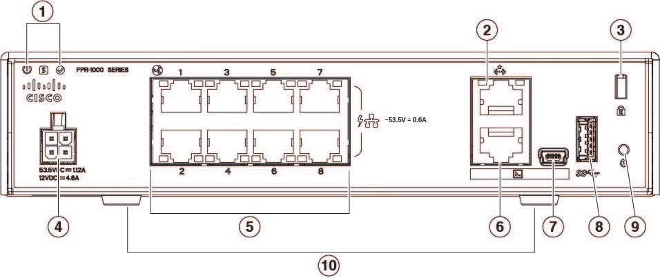
1 | Status LEDs | 2 | Management port |
3 | Lock slot | 4 | Power cord socket |
5 | Network data ports | 6 | Console port |
7 | USB Mini B port | 8 | USB Type A port |
9 | Reset button | 10 | Rubber feet |